History of USB
Universal Serial Bus, or USB, was invented by a consortium of companies (Compaq, DEC, IBM, Intel, Microsoft, NEC, and Nortel) in 1994. The intent was to replace the myriad number of cables that were used at the time to connect a personal computer to all the peripherals. Mice, Keyboards, Joysticks, modems, and printers all had cables with different wiring schemes and different connectors. The release timeline looks like this:
- USB 1.0 introduced in January of 1996, with a data rate of 1.5Mbits/s
- USB 1.1 released in September of 1998, with a data rate of 12Mbits/s
- Apple releases the iMAC G3 in August of 1998, drops all legacy ports
- USB 2.0 released in 2001, with a data rate of 480Mbits/s
- USB 3.0 released in 2008 (aka USB 3.1 Gen1), with a data rate of 5Gbits/s
- USB 3.1 released in 2013 (aka USB 3.1 Gen2) with a data rate of 10Gbits/s
- USB 3.2 released in September of 2017 (aka USB 3.1 Gen3) with a data rate of 20Gbits/s
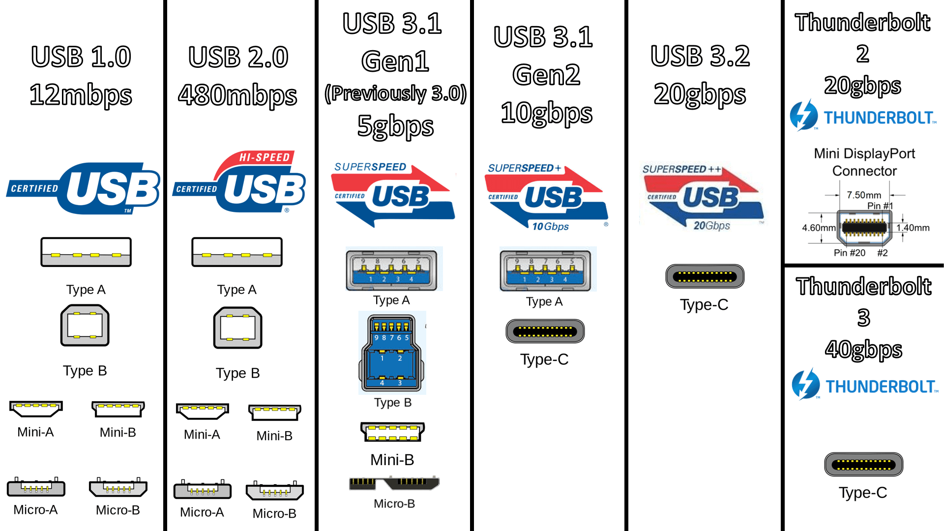
Below is a chart showing the types of connectors that are associated with various revisions of the specifications. The connectors are color coded so that a consumer can recognize which version of USB spec (and speed) the connector will support. The colors are:
- White USB 1.1
- Black USB 2.0
- Blue USB 3.x
- Yellow Charge, or Sleep, allowing power to be available even when host is powered down.
- Red Charge, or Sleep, allowing power to be available even when host is powered down.
Topology and data rates
USB standard began as a Host-Device topology. In almost all cases, the PC is the host, and peripherals are the devices. The standard supports four data transfer types:
- Control, which is the normal mode where the host will periodically poll the device for input or information, examples are mice and keyboards.
- Interrupt, which allows the device to interrupt the host processor and announce there is data available, example is a gaming joystick.
- Bulk, which allows for large-scale data to be transferred, example would be a USB external hard disk.
- Isochronous, which allows for guaranteed access to the bus for data transfer, examples are audio and video streams that are real-time tasks
Why do we care about data rates? Mice and keyboards use only a few kilobytes per second, modems (rare these days) up to 56Kbits/s, external hard disks up to 116Kbits/s, and optimized data transfer to smartphones up to 200Mbits/s. What would need more bandwidth? The answer is digital video. As compressed and uncompressed video rates have soared, there has been a resulting need to increase bandwidth on digital buses to accommodate it. Now that USB 3.2 has arrived with data rates of a blazing 20Gbits/s being available, USB now has the ability (using a type C cable system) to replace all of these connectors:
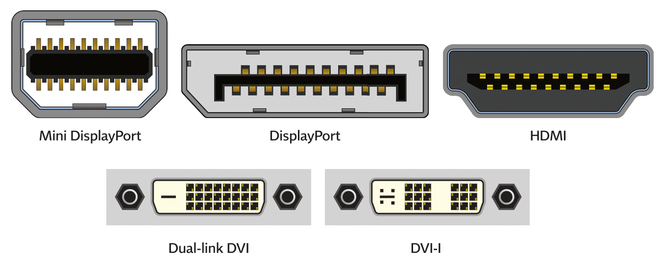
Type C
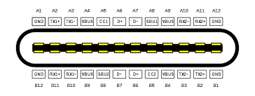
Now we come to the Type C connector. This connector is often confused with a particular standard, such as USB 3.1. But Type-C is a connector/cable topology, and is a standalone part of the USB specification. The Type C connector can support functions ranging from USB 2.0 all the way up to the Thunderbolt at 40Gbits/s. Because a completely new connector/cable topology was needed to support digital video streams, USB Org came up with a topology that allows:
- Reversible Connector – you can plug it in rightside up or upside down and it will work. No more fumbling and trying to check the cable/port orientation before attempting to join.
- Reversible Cable – on a full-feature USB 3.1 cable using Type C on both ends, the host and device will configure themselves automatically, such that the cable does not care which end faces which host/device.
- Four twisted-pair data paths – cable can now carry video signals as in standard industry digital video cables/connectors. Because of the four data pairs, it can also carry network traffic normally reserved for the CAT-series of cables (CAT5, CAT6, etc.)
- It can also support power at 5A of current (with E-Marking), so with Power Delivery host and device, can carry up to 100W of power.
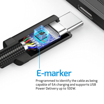
E-Marking
E-Marking is required when a Type-C cable supports either 5A, or full function (5A is a subordinate standard to full function). The E-Mark identifies the micro controller embedded in the connector which performs the negotiation with the host. The cable, in essence, will advertise that it has several wires that are available for for power usage and can handle 5A of current.
Power Delivery
Power Delivery (PD) is an addendum to the USB spec which allows for higher wattage power to be supported by the topology. Historically, USB’s ability to supply power to a device was fairly limited, because there was only a single wire for power and a single wire for ground.
- USB 1.1 was a maximum of 0.5W (500ma @ 5V)
- USB 2.0 was a maximum of 10.5W (2.1A @ 5v), also popular for servicing the charging needs of the Apple iPad
- USB 3.x moves up to 15W (3A @5V)
- USB PD (with E-Mark) allows from 25W (5A @ 5v) to 100W (5A @ 20V).
With the Power Delivery negotiation protocol, the host and device can negotiate as to who will be the power user and the power supply. They can negotiate as to how much power one side can provide, and how much power the other side will need. If more than 25W is required, the voltage is ramped up to a maximum of 20 volts to provide up to 100W of power. This is enough power to fully power a laptop workstation.
On the Go
The On The Go standard (OTG) allows a USB node to be both a host OR a device, depending upon how it is connected. This allows a smart phone, for example, to be plugged into a PC as a device uploading photos, or to be plugged into a USB stick as a host, to download photos. The system uses an extra wire in the cable to identify host/device, and power user/supplier. It is available in USB 2.0 standard and up.
Use Cases for Type-C
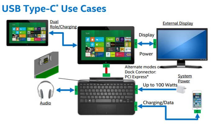
In the modern computing system, a USB Type-C cable can be used for every single cable needed. Monitors can provide power to PCs. Keyboards can supply power to Tablets, and can host smartphones with both data and charging. More and more manufacturers are creating Type-C enabled devices and in the future this may well become the only cable topology the consumer needs to have.
If you have any further questions, please visit: https://summitech.com/contact/